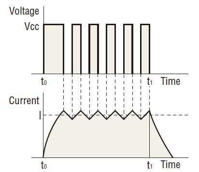
There are two common systems of driving a stepper motor: constant current drive and constant voltage drive. The circuitry for the constant voltage drive is simpler, but it is relatively more difficult to achieve torque performance at high speeds.
The constant current drive, on the other hand, is now the most commonly used drive method, since it offers excellent torque performance at high speeds. All ATO stepper motor drivers use the constant current drive system.

Constant current drive system
The stepper motor rotates through the sequential switching of current flowing through the windings. When the speed increases, the switching rate also becomes faster and the current rise falls behind, resulting in lost torque.
The chopping of a DC voltage that is far higher than the motor’s rated voltage will ensure the rated current reaches the motor, even at higher speeds.

The current flowing to the motor windings, detected as a voltage through a current detecting resistor, is compared to the reference voltage. Current control is accomplished by holding the switching transistor Tr2 ON when the voltage across the detecting resistor is lower than the reference voltage (when it has not reached the rated current), or turning Tr2 OFF when the value is higher than the reference voltage (when it exceeds the rated current), thereby providing a constant flow of rated current.

Difference between AC input and DC input characteristics
A stepper motor is driven by a DC voltage applied through a driver. In ATO 24 VDC input motor and driver packages, 24 VDC is applied to the motor. In the 100-115 VAC motor and driver packages the input is rectified to DC and then approximately 140 VDC is applied to the motor. (Certain products are exceptions to this.) This difference in voltages applied to the motors appears as a difference in torque characteristics at high speeds. This is due to the fact that the higher the applied voltage is, the faster the current rise through the motor windings will be, facilitating the application of rated current at higher speeds. Thus, the AC input motor and driver package has superior torque characteristics over a wide speed range, from low to high speeds. It is recommended that AC input motor and driver packages, which are compatible with a wider range of operating conditions, be considered for applications.

Microstep technology
Microstep drive technology is used to divide the basic step angle (0.72) of the 0.72° stepper motor into smaller steps (up to a
maximum of 250 divisions) without the use of a speed reduction mechanism.
- Features
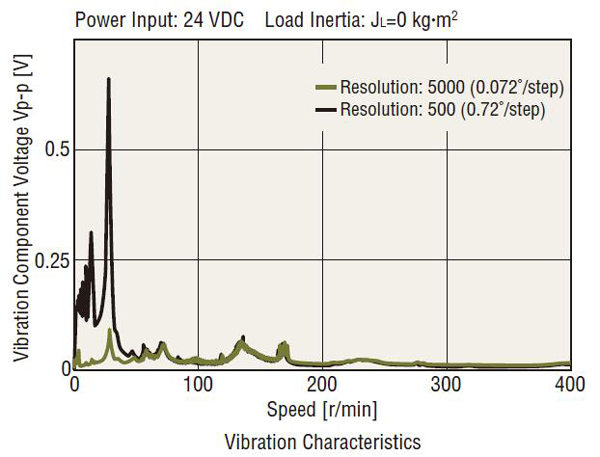
The stepper motor moves and stops in increments of the step angle determined by the rotor and stator’s salient pole structure, easily achieving a high degree of precision in positioning. The stepper motor, on the other hand, causes the rotor speed to vary because the motor rotates in step angle increments, resulting in resonance or greater vibration at a given speed.
Microstepping is a technology that achieves low resonance, low noise operation at extremely low speeds by controlling the flow of electric current fed to the motor coil and thereby dividing the motor’s basic step angle into smaller steps.- The motor’s basic step angle (0.72/full step) can be divided into smaller steps ranging from 1/1 to 1/250. Microstepping thus ensures smooth operation.
- With the technology for smoothly varying the motor drive current, motor vibration can be minimized for low noise operation.
- Up to 250 microsteps based on basic step angle
Thanks to the microstep driver, different step angles (16 steps up to 250 divisions) can be set to two step angle setting switches. By controlling the input signal for step angle switching via an external source, it is possible to switch the step angle between the levels set for the respective switches.
Features of microstep drive
- Low vibration
Microstep drive technology electronically divides the step angle into smaller steps, ensuring smooth incremental motion at low speeds and significantly reducing vibration. While a damper or similar device is generally used to reduce vibration, the low vibration design employed for the motor itself – along with the microstep drive technology – minimizes vibration more effectively. Anti-vibration measures can be dramatically simplified, so it is ideal for most vibration sensitive applications and equipment.

- Low noise
Microstep drive technology effectively reduces the vibration related noise level at low speeds, achieving low noise performance. The motor demonstrates outstanding performance in even the most noise sensitive environment. - Improved controllability
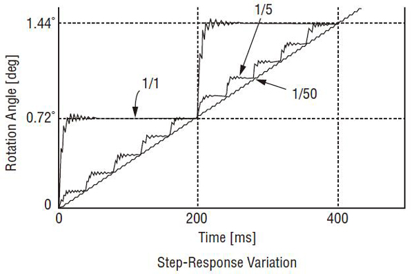
The ATO microstep driver, with its superior damping performance, minimizes overshoot and undershoot in response to step changes, accurately following the pulse pattern and ensuring improved linearity. In addition, shock normally resulting from the motions of starting and stopping can be lessened.
