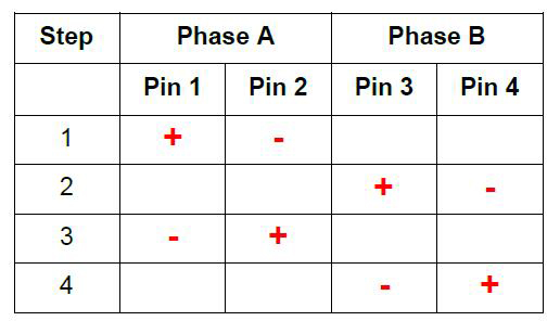
Figure 1 shows a simplified schematic of the operation for a two-phase permanent magnet stepper motor and Figure 2 the corresponding energizing sequence of the coils (clockwise rotation). For a counterclockwise rotation, the sequence must be reversed.
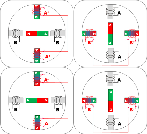
As one coil is energized, a magnetic field is created and attracts the North or South pole of the magnet, depending on the polarity of the energized coil. By alternatively energizing the different coils (giving birth to a sequence), it is then possible to rotate the magnet.
Usually, stepper motors have 2 phases, but some of them may also have 3 or 5 phases.
Bipolar stepper motors usually use one winding per phase because the current in the winding can be made to circulate in both directions. Unipolar stepper motors use one winding per phase with a tap in the middle; hence, half of the winding is used for positive current flow and half for negative current flow (corresponding to two separate coils). ATO designs and manufactures only bipolar stepper motors. A pole is defined as a region where the magnetic flux density is concentrated. It corresponds to the North or the South “pole” of a magnet. ATO stepper motors feature either 10 or 12 poles (corresponding to 5 or 6 pole pairs) in combination with 2 phases, which leads to 20 or 24 steps per revolution.
The step angle is determined by the number of steps, for instance a stepper motor with 20 steps will define a step angle of 18°(=360°/20).
Step angle = 360 / NPh · Ph = 360 / N
Where
- NPh = number of equivalent poles per phase = number of rotor poles
- Ph = number of phases
- N = total number of poles for all phases together
One phase-on and Two phase-on
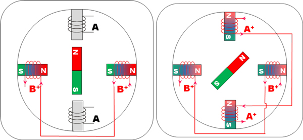
There are two main ways to energize a stepper motor (when operating in full steps). Either 1 phase is energized at a time (“1 phase-ON” configuration) or 2 phases are energized at the same time (“2 phase-ON” configuration). For the “1 phase-ON” configuration, the commutation sequence is A+=> B+=> A-=> B- for a direction and A+=> B-=> A-=> B+ for the opposite rotation direction. For the “2 phase-ON” configuration, the sequence is A+B+=> A-B+=> A-B-=> A+B- for one direction of rotation and A+B+=> A+B-=> A-B-=> A-B+ for the other direction.
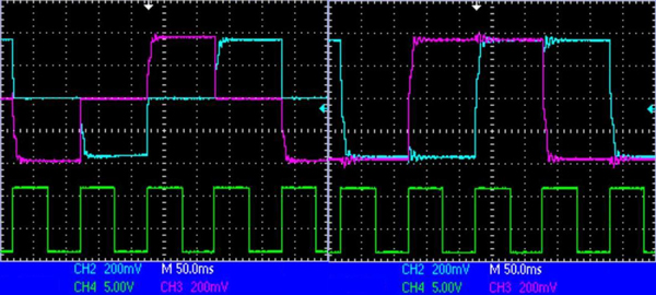
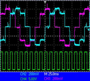
The evolution across time of both phase current signals for each type of configuration is different, as illustrated in Figure 4. The clock pulse signal (green), corresponding to the commutation speed, determines the rotation speed of the rotor. If the same torque of both “1 phase-ON” and “2 phase-ON” configurations is required, then the current applied in the “1 phase-ON” configuration must be √2 times higher than the cur-rent applied in the “2 phase-ON” configuration (same power consumption).
To understand why the current must be √2 times higher in 1 phase-ON operation to obtain the same torque than in 2 phase-ON operation, Figure 9 below can help:

When 2 phases are energized at a time, the sum of the vector equals √2 times the separate value of one phase, which explains why the current in 1 phase-ON must be higher to obtain the same torque at the out-put.
Full-stepping and half-stepping
When alternating both “1 phase-ON” and “2 phase-ON” operations, the rotor can achieve half-steps. The commutation sequence is thus given by A+=>A+B+=>B+=>B+A-=>A-=>A-B-=>B-=>B-A+, which is twice the number of steps obtained with full-step operation, the step angle also being halved. For counter-clockwise rotation, the sequence is just reversed. If the same torque between each half step is required, then the current applied in the “1 phase-ON” configuration must be √2 times higher than the current applied in the “2 phase-ON” configuration.
Micro stepping
For operation at low speed (typically below 600 rpm) or if a resolution of less than a half-step is required, micro stepping is the ultimate solution. By properly energizing the windings, it is possible to move the rotor less than a degree. Most drivers can support such an operating mode .The idea is to energize two coils in such a way, that the rotor will position itself according to a smaller step angle. By extension, supplying each phase current in form of a sine wave allows the stepper motor to achieve a very high degree of resolution. Such an operating mode is explained in more detail in the separate micro stepping application note.

