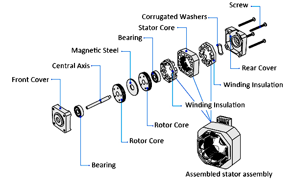
Stepper motor is an open-loop control element stepper motor that converts electrical pulse signals into angular displacement or linear displacement. By controlling the sequence, frequency and number of electrical pulses applied to the motor coil, the steering, Control of speed and rotation angle. With linear motion actuator or gear box device, more complex and precise linear motion control requirements can be achieved. Stepping motors are generally composed of front and rear covers, bearings, central shafts, rotor cores, stator cores, stator components, corrugated washers, screws, etc. Stepping motors are also called steppers. The conversion into mechanical energy is driven by coils wound around the slots of the motor’s stator. Typically, a piece of wire wound in a loop is called a solenoid, while in a motor, the wire wound around the slots of the stator is called a winding, coil, or phase.

How does a stepper motor work?
According to the external control pulse and direction signal, the stepping motor driver controls the winding of the stepper motor to energize forward or reverse in a certain sequence through its internal logic circuit, so that the motor rotates forward/ reversely, or locks.
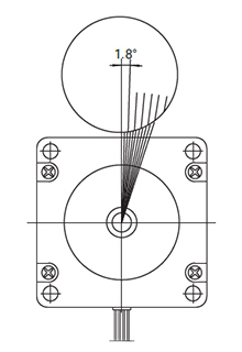
Take a 1.8 degree two-phase stepper motor as an example: when both phase windings are energized and excited, the motor output shaft will be stationary and locked in position. The maximum torque that keeps the motor locked at rated current is the holding torque. If the current in one of the phase windings changes direction, the motor will rotate one step (1.8 degrees) in a given direction. Similarly, if the current of the other winding changes direction, the motor will rotate one step (1.8 degrees) in the opposite direction to the former. When the current passing through the coil windings changes to the excitation direction in sequence, the motor will realize continuous rotation and step in the given direction, and the running accuracy is very high. For a 1.8-degree two-phase stepper motor, it takes 200 steps to make one revolution.
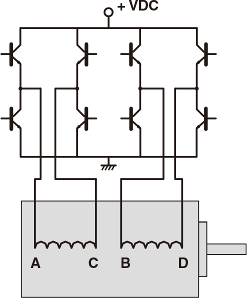
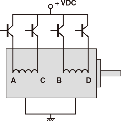
Two-phase stepper motors have two types of windings: bipolar and unipolar. There is only one winding coil on each phase of the bipolar motor. When the motor rotates continuously, the current needs to change the direction of excitation in the same coil in turn. The drive circuit design requires eight electronic switches to switch in sequence. There are two winding coils with opposite polarities on each phase of a unipolar motor. When the motor rotates continuously, it is only necessary to alternately energize and excite the two winding coils on the same phase. Only four electronic switches are required in the drive circuit design. In bipolar drive mode, because the winding coils of each phase are 100% excited, the output torque of the motor in bipolar drive mode is about 40% higher than that in unipolar drive mode.


Precise position control
The stepper motor rotates at a fixed step angle, like the second hand in a clock. This angle is called the basic step angle. ATO sells different series of stepper motor, including Nema 17, Nema 23, Nema 24, Nema 34 and Nema 42 stepper motor with a basic step angle of 1.8°.
