A stepper motor driver receives low-level signals from a controller/indexer and converts them into electrical winding currents to run a stepper motor. One step pulse into the driver is required for every step of the motor shaft. In full-step mode, with a standard 200 step motor it takes 200 step pulses to complete one revolution; in half-step mode it would take 400. In microstepping modes the driver would be generate many more step pulses per revolution – 16X mode would require 3200 steps and 256x mode would require 51,200.
It is generally accepted that increasing microstepping accuracy is limited to about 16x microstepping, but greater microstepping can continue to improve smoothness in slower motion situations.
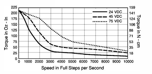
Speed and torque performance of the step motor is based on the flow of current from the driver to the motor winding. The factor that inhibits the flow, or limits the time it takes for the current to energize the winding, is known as motor winding inductance. The lower the inductance, the faster the current gets to the winding and the better the performance of the motor. To reduce the effects of motor inductance, most stepper motor drivers are designed to supply a voltage much greater than the motor’s “rated” voltage. The higher the applied voltage, the higher the maximum speed of the system at maximum step rate.
For industrial applications there are several types of driver technologies. They all utilize a “translator” to convert the step and direction signals from the controller into electrical pulses to the motor – this translator converts then amplifies the signal to generate the required winding currents. The essential difference is in the way they energize the motor windings.
Unipolar Stepper Motor Driver
The name unipolar is derived from the fact that current flow is limited to one direction for each motor drive signal, and as such it necessarily requires a unipolar stepper motor (see motor types). Because of the simplicity of switching current in one direction, the unipolar drive is fairly simple and inexpensive. The drawback to using a unipolar drive, however, is its limited capability to energize all windings at one time. As a result, the number of amp-turns (torque) is reduced by nearly 40% compared to other driver technologies. Unipolar drivers are acceptable for low step rates and lower torque.
Bipolor Stepper Motor Driver
Bipolar chopper drivers are by far the most widely used drivers for industrial applications. Although they are typically more expensive to design, they offer high performance and high efficiency. Bipolar chopper drivers use an extra set of switching elements to eliminate the need for two power sources; a “chopping” effect is utilized to maintain the correct current drive to the motor during all drive stages and through microstepping modes.
Driver and Motor Wiring Configurations
Stepping motors typically come with 4, 6, or 8 leads. With respect to wiring a motor to the driver, let us only consider bipolar drives (AMS supplies only bipolar drivers and driver-controller systems). The driver will typically feature 4 connections to connect the motor: an A and B connection for each of the 2 phases – each phase output pair is independent, so wiring up a 4-lead unifilar motor is therefore straightforward.
For bipolar (bifilar-wound) motors, there are more options for connection. When driving with standard drivers to bifilar motors with 8 leads, the coils can either be connected in series or in parallel, as shown right. A series connection provides a high inductance and therefore greater performance (higher torque) at low speeds. A parallel connection will lower the inductance but increase the torque at higher speeds. The following is a typical speed/torque curve for an AMS driver and motor connected in series and parallel:

In case of a six-lead motor, the performance at higher speeds can be improved by using the half-winding configuration. This comes at the price of reduced torque at lower and mid-range speeds. However, due to the reduced inductance, performance at higher speeds is improved. Six-lead motors were used most commonly with unipolar drivers, which used currents from the center lead of each phase to alternate ends of the winding – this method only uses half the motor winding at any one time. To get maximum torque on one, drive the ends of the winding and insulate (don’t connect) the center taps.
Phase Current
An important parameter in the selection or design of the driver is the current it sends through the coils of the motor. The current specified for the motor is the maximum current that is allowable per phase. To avoid damage to the motor ensure that this current is not exceeded. Many drives allow limiting the current either by potentiometer, DIP switches, or by soft setting through the controller. Because stepper motors run hot it is advisable to use a current that is as low as possible while still maintaining reliable motion. This means that in many applications the maximum phase current set can and will be lower than that allowed by the motor or driver specs. This will help to maximize the lifetime of motor and driver hardware.

Note that many drivers and driver/controller systems have Automatic Idle Reduction feature, which can reduce the drive current during idle or ‘hold’ situations automatically to a lower drive current than during standard motion. Some systems provide independent idle-current and run-current settings, others set idle current as a percentage of run current, and still others cut off current during idle (zero current). Each situation requires consideration of idle/hold current requirements.
