It is important that the stepper motor develop enough torque with each step to drive the load. If it doesn’t, the motor will stall (not step). When steps are missed, the controller no longer knows the exact position of the load, which may render the system useless.
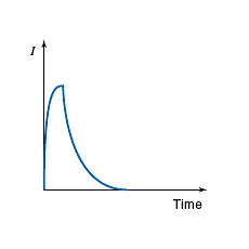
At higher stepping rates, two problems occur. First, if the load is accelerating, extra torque is needed to overcome inertia; second, the available motor torque actually diminishes at higher speeds. Recall that motor torque is directly proportional to motor current and that the average current decreases as the stepping rate increases.

To improve the torque, there are 3 methods: ballast resistors, bilevel drive, constant current chopper drive.
Ballast resistors, to reduce the time constant.
τ = L / R
Where
τ = Time constant
L = Motor inductance
R = Motor coil resistance


Bilevel drive
In this approach, a high voltage is momentarily applied to the stepper motor at the beginning of the step to force a fast in-rush of current. Then a lower voltage level is switched on to maintain that current.
When the desired current level is reached, the 25-V circuit is switched off, and the 12-V circuit is switched on, which keeps the current at the desired level for the rest of the step time.
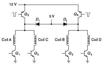
Figure shows a bilevel-drive interface circuit. In this case, the higher voltage is 12 V, and the lower voltage is 5 V. The 12-V is switched through either Q5 or Q6 in response to a pulse from a timing circuit (not shown). The 5-V is applied through D1 and D2. These diodes keep the 12-V pulses from backing up into the 5-V power supply.
The bilevel drive is more complex but allows the stepper motor to have more torque at higher stepping rates.


Constant current chopper drive
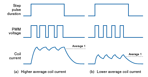
Using PWM techniques, this driver circuit can deliver almost the same current to the motor at all speeds. A chopper-drive waveform works in the following manner: A relatively high voltage is switched to the motor coil, and the current is monitored. When the current reaches a specified level, the voltage is cut off. After a short time, the voltage is reapplied, and the current again increases, only to be cut off, and so on. Thus, in the same way that a thermostat can maintain a constant temperature by switching the furnace on and off, the chopper drive maintains a constant average current (within each drive pulse) by rapidly switching the voltage on and off.
In summary, the chopper drive is another technique for providing good torque at high stepping rates. Stepper motor driver ICs are available, such as the Allegro A2919SB, with built-in PWM constant current capability.
