An important point to consider in the application of stepper motors is whether the motor characteristics are suitable to the operating conditions.
The following describes the characteristics to be considered in the application of stepper motors. The two main characteristics of stepper motor performance are:
- Dynamic Characteristics
These are the starting and rotational characteristics of a stepper motor, mainly affecting the machinery’s movement and cycling time. - Static Characteristics
These are the characteristics relating to the changes in angle that take place when the stepper motor is in standstill mode, affecting the machinery’s level of precision.

Dynamic Characteristics
Speed – Torque Characteristics
The figure above is a characteristics graph showing the relationship between the speed and torque of a driven stepper motor. These characteristics are always referred to in the selection of a stepper motor. The horizontal axis represents the speed at the motor output shaft, and the vertical axis represents the torque. The speed – torque characteristics are determined by the motor and driver, and are greatly affected by the type of driver being used.
- Maximum holding torque (TH)
The maximum holding torque is the stepper motor’s maximum holding power (torque) when power is supplied (at rated current) when the motor is not rotating. - Pullout torque
The pullout torque is the maximum torque that can be output at a given speed.
When selecting a motor, be sure the required torque falls within this curve. - Maximum starting frequency (fs)
This is the maximum pulse speed at which the motor can start or stop instantly (without an acceleration/deceleration time) when the stepper motor’s friction load and inertial load are 0.
Driving the motor at a pulse speed in excess of this rate will require a gradual acceleration or deceleration. This frequency will decrease when an inertial load is added to the motor.
Refer to the inertial load – starting frequency characteristics below. - Maximum response frequency (fr)
This is the maximum pulse speed at which the motor can be operated through gradual acceleration or deceleration when the stepper motor’s friction load and inertial load are 0.
The figure below shows the speed – torque characteristics of a 0.72°

Inertial Load – Starting Frequency Characteristics
These characteristics show the changes in the starting frequency caused by the load inertia. Since the stepper motor’s rotor and load have their own moment of inertia, lags and advances occur on the motor axis during instantaneous starting and stopping. These values change with the pulse speed, but the motor cannot follow the pulse speed beyond a certain point, so that missteps result. The pulse speed immediately before the occurrence of a misstep is called the starting frequency.

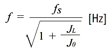
Changes in maximum starting frequency with the inertial load may be approximated via the following formula:

fs: Maximum starting frequency of motor [Hz]
f: Maximum starting frequency where inertial load is present [Hz]
J0: Moment of inertia of rotor [kg·m2 (oz-in2)]
JL: Moment of inertia of load [kg·m2 (oz-in2)]
Vibration Characteristics
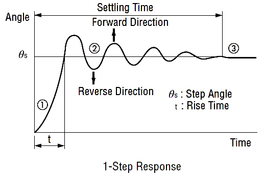
The stepper motor rotates through a series of stepping movements. A stepping movement may be described as a 1-step response, as shown below:
- A single pulse input to a stepper motor at a standstill accelerates the motor toward the next stop position.
- The accelerated motor rotates through the stop position, overshoots a certain angle, and is pulled back in reverse.
- The motor settles to a stop at the set stop position following a damping oscillation.

Vibration at low speeds is caused by a step-like movement that produces this type of damping oscillation. The vibration characteristics graph below represents the magnitude of vibration of a motor in rotation. The lower the vibration level, the smoother the motor rotation will be.

Static Characteristics
Angle – Torque Characteristics
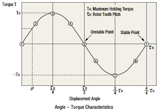
The angle – torque characteristics show the relationship between the angular displacement of the rotor and the torque externally applied to the motor shaft while the motor is excited at the rated current. The curve for these characteristics is shown below:

The following illustrations show the positional relationship between the rotor teeth and stator teeth at the numbered points in the
diagram above.
When held stable at point ① the external application of a force to the motor shaft will produce torque T (+) in the left direction, trying to return the shaft to stable point ①. The shaft will stop when the external force equals this torque at point ②.
If additional external force is applied, there is an angle at which the torque produced will reach its maximum at point ③. This torque is called the maximum holding torque TH. Application of external force in excess of this value will drive the rotor to an unstable point ⑤ and beyond, producing torque T (-) in the same direction as the external force, so that it moves to the next
stable point ① and stops.

Stable Points
Points where the rotor stops, with the stator teeth and rotor teeth are exactly aligned. These points are extremely stable, and the rotor will always stop there if no external force is applied.
Stable Points
Points where the rotor stops, with the stator teeth and rotor teeth are exactly aligned. These points are extremely stable, and the
rotor will always stop there if no external force is applied.
Unstable Points
Points where the stator teeth and rotor teeth are half a pitch out of alignment. A rotor at these points will move to the next stable point to the left or right, even under the slightest external force.
Angle Accuracy
Under no load conditions, a stepper motor has an angle accuracy within 士 3 arcminutes (±0.05 ). The small error arises from the
difference in mechanical precision of the stator and rotor and a small variance in the DC resistance of the stator winding. Generally, the angle accuracy of the stepper motor is expressed in terms of the stop position accuracy, as described on the right.
Stop Position Accuracy
The stop position accuracy is the difference between the rotor’s theoretical stopping position and its actual stopping position. A
given rotor stopping point is taken as the starting point, then the stop position accuracy is the difference between the maximum (+) value and maximum (-) value in the set of measurements taken for each step of a full rotation.

The stop position accuracy is within 士 3 arcminutes (+ 0.05° ), but only under no load conditions. In actual applications there is always the same amount of friction load. The angle accuracy in such cases is produced by the angular displacement caused by the angle – torque characteristics based upon the friction load. If the friction load is constant, the displacement angle will be constant for uni-directional operation. However, in bi-directional operation, double the displacement angle is produced over a round trip. When high stopping accuracy is required, always position in the same direction.
If you want more information about oil pipe stepping motors, you can understand it at ATO Industrial Automation.