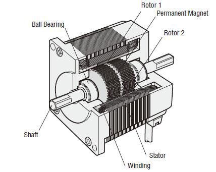
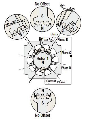
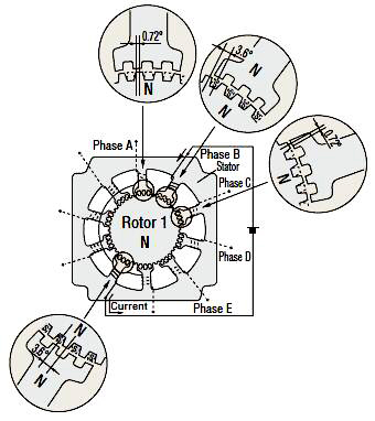
The figures below show two cross-sections of a 0.72° stepper motor. The stepper motor consists primarily of two parts: a stator and rotor. The rotor is made up of three components: rotor 1, rotor 2 and a permanent magnet. The rotor is magnetized in the axial direction so that, for example, if rotor 1 is polarized north, rotor 2 will be polarized south.

The stator has ten magnetic poles with small teeth, each pole being provided with a winding. Each winding is connected to the winding of the opposite pole so that both poles are magnetized in the same polarity when current is sent through the pair of windings. (Running a current through a given winding magnetizes the opposing pair of poles in the same polarity, i.e., north or south.) The opposing pair of poles constitutes one phase. Since there are five phases, A through E, the motor is called a “0.72° stepper motor.’ With a 1.8° or 0.9° stepper motor, there are two phases, A and B. These 2 phase motors are called 1.8° and 0.9° stepper motors. There are 50 small teeth on the outer perimeter of each rotor, with the small teeth of rotor 1 and rotor 2 being mechanically offset from each other by half a tooth pitch.
Excitation: To send current through a motor winding.
Magnetic pole: A projected part of the stator, magnetized by excitation.
Small teeth: The teeth on the rotor and stator.


Stepper motor’s principle of operation
Following is an explanation of the relationship between the magnetized stator small teeth and rotor small teeth.
When phase “A” is excited
When phase A is excited, its poles are polarized south. This attracts the teeth of rotor 1, which are polarized north, while repelling the teeth of rotor 2, which are polarized south. Therefore, the forces on the entire unit in equilibrium hold the rotor stationary. At this time, the teeth of the phase B poles, which are not excited, are misaligned with the south-polarized teeth of rotor 2 so that they are offset 0.72°. This summarizes the relationship between the stator teeth and rotor teeth with phase A excited.

When phase “B” is excited
When excitation switches from phase A to B, the phase B poles are polarized north, attracting the south polarity of rotor 2 and repelling the north polarity of rotor 1.

In other words, when excitation switches from phase A to B, the rotor rotates by 0.72°. As excitation shifts from phase A, to phases B, C, D and E, then back around to phase A, the stepper motor rotates precisely in 0.72% steps. To rotate in reverse, reverse the excitation sequence to phase A, E, D, C, B, then back around to phase A. The high resolution of 0.72° is inherent in the mechanical offset between the stator and rotor, accounting for the achievement of precise positioning without the use of an encoder or other sensors. High stopping accuracy of +3 arc minutes (with no load) is obtained, since the only factors affecting stopping accuracy are variations in the machining precision of the stator and rotor, assembly precision and DC resistance of windings. The driver performs the role of phase switching, and its timing is controlled by a pulse-signal input to the driver. The previous example shows the excitation advancing one phase at a time, but in an actual stepper motor an effective use of the windings is made by exciting four or five phases simultaneously.