This article will show the basic circuits needed to drive the various types of stepper motors. These control circuits will be expanded below to include current limiting considerations.
Variable Reluctance Stepper Motor
Variable reluctance motors have multiple windings, typically three to five, which are all tied together at one end. The windings are turned on one at a time in a particular sequence to turn the motor.
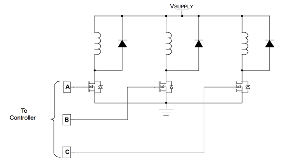
Figure 1 shows the basic circuit for driving a variable reluctance motor. Note the diodes across the windings. As with all inductive loads, as voltage is switched on across a winding, the current in the winding begins ramping up. When the switching transistor for the winding is turned off a voltage spike is produced that can damage the transistor. The diode protects the a transistor from the voltage spike assuming the diode is adequately sized.

Unipolar Stepper Motor
The basic control circuit for a unipolar motor, shown in Figure 2, is similar to that for a variable reluctance stepper motor. Note the extra diodes across each of the transistors. These are necessary because the inductor is center tapped in unipolar motors. When one end of the motor winding is pulled down, the other end will rise and visa versa. These diodes prevent the voltage from falling below ground across the transistors.
Some transistors have integral diodes that allow reverse current to flow unimpeded, regardless of the gate voltage. If such transistors are used, and if these integral diodes have sufficient current carrying capacity to carry the full motor current, the lower diodes shown in Figure 2 can be omitted. All of the diodes must have switching speeds comparable to the speed of the transistors.

Bipolar Stepper Motor
The basic circuit for driving the windings of a bipolar stepper motor is the H-bridge, shown in Figure 3. An H-bridge can be configured to allow current to flow in either direction across a winding. Referring to Figure 9, current will flow from left to right in Winding 1 when transistors Q1 and Q4 are turned on while Q2 and Q3 are off. Current will flow from right to left when Q2 and Q3 are on while Q1 and Q4 are off.
Transistors Q2 and Q4 are N-channel transistors and therefore require a positive bias on turn-on. Q1 and Q3 are P-channel transistors, requiring a negative bias to turn-on. An alternate H-bridge design uses identical transistors for all 4 transistors, and uses charge-pump and level shifting circuitry to drive the gates of the upper transistors shown in Figure 3.
H-bridges have one inherent danger that should be mentioned. Under no circumstances should the transistors on the same side of the bridge be switched on at the same time. This will cause a short which will damage the control circuit. Special care should be made to switch all transistors off before turning the next set of transistors on.
The diodes in parallel with each of the transistors protect the transistors from voltage spikes caused by switching the inductor. These diodes must adequately sized in order to prevent damage to the transistor or diode itself.
As pointed out for unipolar motors, some transistors have integral diodes; in fact, these are shown in the schematic representation for transistors used in Figure 3; if these are able to conduct the full motor current, the additional diodes shown in the figure can be omitted.
