Stepper motors are typically used in open loop in positioning systems. We saw an example similar to the one presented in Fig. 8.1, where an acquisition of the rotor position and speed are shown. The large overshoot of over 50 % can be easily appreciated, followed by several oscillations. Looking at the speed, the rotor reaches again large values compared to the average speed, which in this case with 40 steps per second is 1.25 rad/sec, whereas the peak values reach 25 and -20 rad/sec.
Peak values reach 25 and -20 rad/sec. In the LHC collimators, this jittery movement is tough for the mechanics. The worm screw connected to the motor to move the collimator jaw linearly wears and after a few years of use can need to be replaced, an expensive intervention. It is therefore desirable to attempt to extend its lifespan. This could be achieved with a smoother motion profile applied with the motor. To attain such a profile, closed-loop position control is proposed using Field Oriented Control (FOC).
However, it was claimed that relying on position sensors, as needed for FOC, for critical operation, as is the case of the collimation system, is preferably avoided in the LHC collimators, since it would reduce the reliability of the whole system. A sensor failure could lead to the malfunctioning of the collimator, and thus to the beam dump and stop of the machine. The cost of such an event, plus the required maintenance of the collimator, is not affordable. Sensorless control as presented article is an attractive option, but it has the problem of the loss of observability when the rotor is stopped or at low speed. In the case of the collimators, these are the most common cases, and therefore sensorless estimation is not a reliable option to close the position loop. This fact does not interfere with its use for the purpose of mechanical health diagnostics, since the torque estimation is good during the parts of the motion profiles with non-zero speeds.

To overcome these problems and take advantage of the smoother motion profile that can be achieved using a sensor and closing the position loop, but not reduce the reliability of the system, an automatic closed-to-open position loop switch is proposed. This switch is an original contribution of this thesis. With it, the motor can work in closed-loop position control, providing smooth motion profiles, but in the case of sensor failure, the loop is opened, continuing to work in standard open-loop position control. The sensors can be repaired during the next programmed machine technical stops, allowing for a continuous operation of the collimators and enlarging the collimator mechanics lifespan thanks to the smooth motion while the sensors are working.
A non-negligible trend in research is using stepper motors with the position loop closed in different ways, whether it be with a position sensor or with sensorless techniques. In this chapter the different control strategies that are known to give good performance when applied to stepper motors and the state of the art of the chosen one for this work, FOC, are presented. In the next chapter, the position control scheme and the closed-to-open position loop switch is presented, as well as its application in the LHC collimators at CERN.
There are multiple control approaches for electric motor control for academic and industrial references. Some of the most commonly used control strategies for AC motors have been explored for use in stepper motors.
Closed-loop position control
Field Oriented Control
The operating principle of FOC is relatively simple: a change of coordinates for the electric and magnetic signals are applied from the static reference frame linked to the stator phases to the rotating frame linked to the rotor, where the torque produced is directly proportional to the current in one of the axis of this rotating frame, making its control relatively straightforward with closed-loop control.
FOC is the most popular control strategy for AC motors. It is used to control the torque of the motor, and the speed and position control layers are built on top of the torque control. FOC became standard in induction machines achieving high dynamics, close to DC motor drives. The main advantages of FOC are the smooth operation and the fast transient response. It has also been broadly researched for use with synchronous machines and stepper motors.
Direct Torque Control
Direct Torque Control (DTC), considered originally in and, is a method to control the torque in 3-phase AC motors. First the magnetic flux in the motor and the torque are estimated from the phases voltage and current measurements, and then a hysteresis band-limiting control is applied on both stator flux linkage and torque. Depending on the required action the switches in the 3-phase inverter are controlled in such a way that the flux and torque errors return within the tolerance band of the hysteresis comparators.
DTC is becoming one of the standards in AC motor high dynamic control together with FOC. In a performance comparison of both methods is done for induction motors. Even though DTC has been applied successfully to synchronous permanent magnet motor, the references for stepper motor applications are scarce, and to the author’s knowledge is only used in where the method is applied to a 3-phase stepper motor. In DTC and FOC are compared for synchronous motors, concluding that both methods are close in performance and the advantages are application-specific. For steady state positioning FOC nonetheless turns out to have better performance. In some difficulties for DTC working at low rotor speeds are reported. In spite of the possible solutions to this problem, and its advantages with respect to FOC, such as simplicity of implementation and fast torque control, it is not an attractive option for 2 phase stepper motors as proven by the lack of literature. This fact motivated the choice of FOC for closing the position loop.
FOC and DTC are the most common and successful control strategies for closed loop motor control. However, there are other approaches used in specific applications or in different research branches. Some examples are discussed now.
In Fuzzy Logic control is applied to the closed-loop speed control of stepper motors. A standard stepper motor drive is used and the fuzzy controller is implemented in an upper layer, calculating the time between pulses sent to trigger the steps to obtain the desired speed trajectory. The method is proven to work and yield good results but still works in stepping mode so suffers from overshoot.
Neural networks has been applied for speed control of stepper motors. In this paper two neural networks were used, one for identification and other for control, achieving a good performance at low and high speed. The neural network is implemented in a computer, external to the motor drive.
Field Oriented Control
The Field Oriented Control technique, also known as vector control, is based upon the change of coordinates of the motor electrical and magnetic quantities from the fixed reference frame to a rotating reference frame moving with the rotor. In this rotating frame, the signals are represented in the so-called direct and quadrature axes.
Brushed DC motors are popular due to their simplicity of control. In these motors, the phase angle between the phase current and the induced voltage is fixed mechanically by the commutator and the brushes. In AC motors, however, this angle has to be controlled in order to achieve the desired torque generation. Using FOC allows induction and synchronous motors to be driven in a similar way to brushed DC motors, since in the rotating coordinate system the torque produced is proportional to the quadrature current.
It should be noted that before applying the change of coordinates, systems with 3 phases are reduced to a fixed 2 axis reference frame, which here will be referred to as the ab frame, with axis a and b. The transformation from 3-phase to the equivalent 2-phase system is known as the Clarke or αβ transform.
Field oriented control applied to stepper motors
The change of reference frame used in FOC can be applied to HSM as well. It has already been used for HSM control for example in where it is applied with position sensors and where an Extended Kalman Filter is used, with the limitation of not being able to work in standstill due to the loss of observability when the back emfs are low.
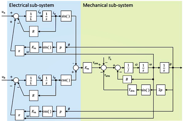
In order to illustrate it in an easier way, its application to a permanent magnet stepper motor (PMSM) is shown now. Then the HSM application can be easily inferred. In Fig. 2 the voltage applied to the motor is represented in both the ab frame, fixed to the stator, and the rotational dq frame, fixed to the rotor.
The discrete equations for the HSM have been discussed in previous article and are repeated here for convenience, but to ease the notation, from this point the currents are assumed to be always the motor currents since only the motor is considered, and not the cable as in the previous articles where we needed to explicitly differentiate between motor and drive currents and voltages. Therefore only the sub-indexes a and b will be used.
From the standard equations representing a stepper motor:
Lia = – Ria + Kmωm sin pθm + ua
Lib = – Rib + Kmωm cos pθm + ub
Jωm = Tem – Bωm – Tdm sin (2pθm + φ) – Tl
θm = ωm
Tem = Km (-ia sin pθm + ib cos pθm)
This standard model is based on the reference frame fixed to Phases A and B. It is possible however to represent voltages and currents in a rotating frame fixed to the rotor, as represented in Fig. 2.


There is a direct link between coordinates in both reference frames. The conversion from the ab frame to the dq frame is called the direct Park Transform:
ua = ua cos (θe) + ub sin (θe)
uq = – ua sin (θe) + ub cos (θe)
And the conversion from the dq to the ab frame is called the inverse Park Transform:
ua = ud cos (θe) + uq sin (θe)
uq = – ud sin (θe) + uq cos (θe)
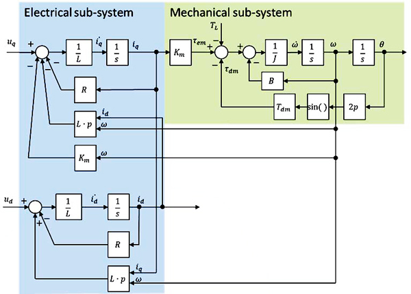
If this conversion, and the equivalent for the currents, the model of the motor in the dq frame is obtained, given by the following
equations and represented in Fig. 4.
Lid = – Rid + pLiqωm + ud
Liq = – Riq – pLidωm + uq – Kmωm
Jωm = Kmiq – Bωm – Tdm sin (2pθm + φ) – Tl
θm = ωm
