The Computer Numerical Control (CNC) is a technology that uses microcomputers to generate, parse and execute the sequential control that describes the end effector’s behavior. The application of this technique is often used in turning, drilling, milling or extruding machines. Recently its application has expanded to other tasks, such as: electronic components insertion, tube welding, and cutting robots. While these technologies are at the top of the third industrial revolution, today we are facing the fourth industrial revolution where one of the main driving forces will be 3D printing.
The idea is to research the possibilities for designing an electro-mechanical system that can be used both as a 3D printer and a CNC machine. The focus in this article is placed on the 3D printer issues, specifically, the synchronized control of 4 or more stepper motors. These results can be reused for CNC milling machines with some additional components.
The starting points are: the mechanical construction, mechanisms for movement and their integration. A 3D model of the machine is shown in figure 1. Speed and forces (torques) calculations define the motors and motor drivers selection. There are various types of printer heads but for this dual-purpose machine a thermal extruder type appears to be the most appropriate. The main controller should be also suitably selected for the dual purpose.
CNC machine motion can be performed with AC or DC servo motors or stepper motors. Servo motors require additional positioning sensors and closed loop control systems. Stepper motors are very accurate in open loop systems and are simple to control provided that the maximal required torque at the maximal required speed is available.

A specific issue regarding motion control is the multiple axes motion synchronization. This is a very complex task with servo motors but is also nontrivial with stepper motors. 3D printer manufacturers have proprietary control algorithms that are not accessible for performing experiments. Open source community projects are available for this purpose but, again, better performing algorithms are usually encapsulated in binary libraries. Some motor and controller manufacturers offer PLC controllers that provide 2-axes synchronization with speed control but PLCs are an expensive overkill with the additional (unnecessary) options they have. They also do not provide solutions for 3 or more axis synchronization. In this paper we present a very efficient algorithm for synchronized stepper motors control that uses small number of operations compared with the algorithm for linear interpolation explained in the literature. The results are based on real experiments with a 3D printer designed from scratch in our laboratory to experiment with different types of stepper motors and algorithms.
Stepper motor drive topologies
The following is the stepper motor operation and their drive topologies. Stepper motors usually have permanent magnet rotor and two (or four) groups of windings on the stator as presented in figure 2. The group of windings is presented as coils at 90 degrees which are called “electrical degrees” while the windings are positioned at certain spatial angle such that a 360° electrical angle corresponds to a much smaller spatial angle (eg. 7.2°).
The rotor is moved by changing the current through the coils in appropriate sequence such that magnetic forces attract or repel the rotor to support the rotation. If the currents through the coils change direction, the motor is named bipolar. Otherwise it is unipolar.


The current is obtained by connecting the coils to a voltage source V through appropriate electronic switches (a stepper motor driver). One step is a sequence of two coils (or four coils) sequentially energized/de-energized (pulsed) and it corresponds to a rotation by a predefined angle (typically 1.8° for a 200-step motor).
The coils resemble first order circuits with their inductance L and resistance R. This means the currents through the coils change exponentially:
i ( t ) = I ( ∞ ) − [ I ( ∞ ) − I ( 0 ) ] e-t/τ
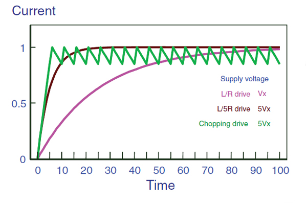
where I ( 0 ) is the starting current, I ( ∝ ) = V / R is the steady state current and τ= L / R is the time-constant of the circuit. A complete current change takes approximately 3τ. This limits the maximal applicable step rate i.e. rotational speed of the motor at full torque because the torque depends on the coil current amplitude – figure 3.
The time-constant can be reduced by increasing R, and correspondingly V, externally by a same factor n (typically 4-5) to retain the nominal current. Unfortunately this increases the power loses nRI2 to an unacceptable level. The solution is the Pulse Width Modulation (PWM) technique which can provide (on average) the nominal coil current at much higher voltage with minimum power loses – figures 4 and 5.


3D printer practical implementation
Besides the previously mentioned electromechanical components, the complete 3D printer includes:
- CAD software for designing and rasterizing the parts to be printed and generating commands in the standard CNC language named G-code
- control unit (microcontroller)
- methods for transferring the G-code to the control unit
- control unit firmware for coordinates calculations and motor driving signals generation
- user interface
The implemented CAD software is Pronterface (free open-source software) with it’s rendering engine Slic3r that slices the part into printable layers. The generated G-code specifies sequence of coordinates for linear X-Y axes movement and the required speed for each movement including the extruder for material deposition as coordinate E. The movement in Z direction is generated only once for each layer to be printed.
G-commands are transferred through serial communication at the rate of 115 kbps. New command is transferred after the current is completed.

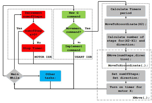
The firmware of the controller consists of many functions (communication, coordinate interpolation, motor control, extruder heating PID control, sensor scan, user interface through a graphical touch-screen, and some other housekeeping functions). Motor control functions are timer interrupt-driven and have the highest priority. Communication is also interrupt driven at a lower level and incorporates the linear interpolation calculations. The lowest interrupt driven function is the PID heater control (not shown here). All other functions are reaized in an infinite loop. The principal block-diagram of the firmware is presented in figure 6.
The current position is tracked through four global variables (X, Y, Z, E) which are updated on each motor step. The target position, sent by the CAD system, is kept in the variables X2, Y2, E2 and speed, (As previously mentioned, Z movement is accomplished separately between layers and will not be discussed here.)
The origin (0,0,0,0) is established at power-up of the machine. The printer moves into negative direction until proximity switches are activated to set the spatial origin (0,0,0) while the extruder coordinate at start-up is 0 by definition.